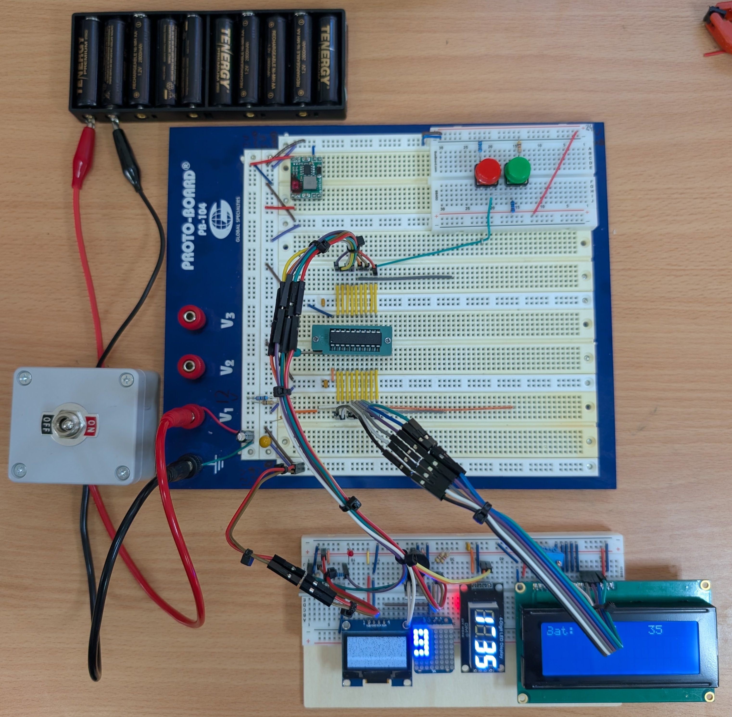
It was time to step up my breadboarding game so I made some improvements. A ZIF socket so I can remove the PIC16 easily. And plenty of space around it so I won't accidentally pull out a jumper.
The input-elements are on their own self-adhesive "island" and all peripherals are on their own detachable block. This block has the most common stuff ready to go and can be made powerless by the MCU when it goes to sleep.
I have a prominently marked, robust on-off switch because when I used a tiny pushbutton I couldn't see whether things were on or off when the system was asleep. And when I slightly rested my finger on it, it already interrupted power.
With the main board having all the standard components in place (5V power module, electrolytics, decoupling capacitors, resistor network to measure battery voltage, the rest of the board is free to put only those extra on that I need for a specific project.
It's very important for any breadboarded circuits that are going to be fiddled with for a long time to be laid out as cleanly as possible so that it remains easy to understand and there is least risk of messing things up. One can go too far however: In my photo there is the risk of crosstalk on the I2C bus due to the long unshielded wires of other signals, packed against them. I did that on purpose, to test the robustness of my I2C bus collision recovery code.